RS232
The Electronics Industry Association (EIA) has
developed standards for data communication. EIA standards where
originally marked with the prefix "RS".
"RS" means that it is a recommended standard, but the
standards are now generally indicated as "EIA" standards.
RS232 was introduced in 1962.
The standard evolved over the years and had the third revision in
1969 (RS-232C).
The fourth revision was in 1987(RS-232D also known as EIA-232D).
RS232 is identical to the standards CCITT V.24/V.28, X.20bis/X.21bis and ISO IS2110.
RS 232 serial port (9-pin) DTE-device (PC)
male connector, female cable connector |


|
|
|
|
|
| PIN |
DESCRIPTION |
|
|
|
|
| 1 |
Data Carrier Detect |
|
| 2 |
Received Data |
|
| 3 |
Transmitted Data |
|
| 4 |
DTE (Data Terminal) Ready |
|
| 5 |
Signal Ground |
|
| 6 |
DCE (Data Set) Ready |
|
| 7 |
Request to Send |
|
| 8 |
Clear to Send |
|
| 9 |
Ring Indicator |
|
RS232 is a voltage loop interface for two-way (full-duplex)
communication represented by voltage levels with respect to system
ground (common). A common ground between the PC and the associated
device is necessary. Maximum serial cable length is defined: 75 feet
at 9,600 bps, but today cables up to 1,000 feet are used successfully.
The interface is single ended (connecting only two devices with
each other), the data rate is less than 20 kbps.
Data:
- logical "1" (Mark) is represented by a negative voltage
of -3V to -25V
- logical "0" (Space) is represented by a positive voltage
of +3V to +25V
Devices that communicate over a serial interface are divided into two classes: DTE and DCE. The most important difference between these types of devices is that the DCE device supplies the clock signal that paces the communications on the bus. All DTE-DCE cables are straight through, the pins are connected one to one. DTE-DTE and DCE-DCE cables are cross cables.
DTE - DCE is called a 'Straight Cable'
DTE - DTE is called a 'Null-Modem Cable'
DCE - DCE is called a 'Tail Circuit Cable'
DTE (Data Terminal Equipment) devices are: computers, terminals, printers, CSU/DSU, Multiplexers. DCE (Data Communications Equipment) devices are: modems and other equipment.
Hubs and Routers could be either DTE or DCE.
The Data Terminal Equipment -DTE- (e.g. regular computer) is normally equipped with a male D-Sub connector, Data Communications Equipment -DCE- equipment with a female connector.
This difference determines, which signal a device expects on which
pin. Any device is configured as either a DTE or a DCE device.
Cables between DTE and DCE are different from cables between DCE and
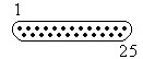
DCE devices. The connector is a 25-pin D-Sub connector (for possible synchronous
communications), or a 9-pin D-Sub connector (the subset for
asynchronous communications). With asynchronous communications the serial data bits are not locked to a specific clock at the receiving end. The bits are
synchronized by the transmit clock at the sending end.
RS232 Data Structure:
25 pin Serial Port RS232
male connector, female cable connector |
 |
| PIN |
DESCRIPTION |
| 1 |
SHIELD |
Ground |
| 2 |
TXD |
Transmit Data |
| 3 |
RXD |
Receive Data |
| 4 |
RTS |
Request to Send |
| 5 |
CTS |
Clear to Send |
| 6 |
DSR |
Data Set Ready |
| 7 |
GND |
System Ground |
| 8 |
CD |
Carrier Detect |
| 9 |
n/c |
(reserved for testing) |
| 10 |
n/c |
(reserved for testing) |
| 11 |
n/c |
|
| 12 |
n/c |
(secondary receive line) |
| 13 |
n/c |
(secondary clear to send) |
| 14 |
n/c |
(secondary transmitted data) |
| 15 |
n/c |
(transmitter signal element timing) |
| 16 |
n/c |
(secondary received data) |
| 17 |
n/c |
(receiver signal element timing) |
| 18 |
n/c |
(local loopback) |
| 19 |
n/c |
(secondary request to send) |
| 20 |
DTR |
Data Terminal Ready |
| 21 |
n/c |
(remote loopback / signal quality detector) |
| 22 |
RI |
Ring Indicator |
| 23 |
n/c |
(data signal rate select) |
| 24 |
n/c |
(transmit signal element timing) |
| 25 |
n/c |
(test mode) |
| Nullmodem Cable 9pin D-Sub
to 9pin D-Sub |
| D-Sub 1, female |
D-Sub 2, female |
| 2 |
Receive Data |
3 |
Transmit Data |
| 3 |
Transmit Data |
2 |
Receive Data |
| 4 |
Data Terminal Ready |
6+1 |
Data Set Ready + Carrier Detect |
| 5 |
System Ground |
5 |
System Ground |
| 6+1 |
Data Set Ready + Carrier Detect |
4 |
Data Terminal Ready |
| 7 |
Request to Send |
8 |
Clear to Send |
| 8 |
Clear to Send |
7 |
Request to Send |
| Nullmodem Cable 25pin D-Sub
to 25pin D-Sub |
| D-Sub 1, female |
D-Sub 2, female |
| 2 |
Transmit Data |
3 |
Receive Data |
| 3 |
Receive Data |
2 |
Transmit Data |
| 4 |
Request to Send |
5 |
Clear to Send |
| 5 |
Clear to Send |
4 |
Request to Send |
| 6+8 |
Data Set Ready + Carrier Detect |
20 |
Data Terminal Ready |
| 7 |
GND |
7 |
GND |
| 20 |
Data Terminal Ready |
6+8 |
Data Set Ready + Carrier Detect |
| Serial 8-pin DIN Connector |
| 8-pin DIN |
Corresponding 25-pin D-Sub |
Signal |
Function |
| 3 |
2 |
TD |
Transmitted data |
| 5 |
3 |
RD |
Received data |
| 6 |
4 |
RTS |
Request to send |
| 2 |
5 |
CTS |
Clear to send |
| 4,8 |
7 |
SG |
Signal ground |
| 7 |
8 |
DCD |
Data carrier detect |
| 1 |
20 |
DTR |
Data terminal ready |
| RS232 to 3.5mm Mini-Jack (walkman headphone style) connection used by many digital cameras to download data to PC |
| 9-pin Connector |
Function |
Mini-Jack |
| 2 |
transmit from device |
Tip |
| 3 |
transmit to device |
Ring |
| 5 |
Ground |
Sleeve |
| RS232 over RJ45 (RS232D) |
 |
| Description |
RJ45 Pin |
| Signal Ground |
4 |
| Transmitted Data |
6 |
| Received Data |
5 |
| Request To Send |
8 |
| Clear To Send |
7 |
| DCE Ready, Ring Indicator |
1 |
| DTE Ready |
3 |
| Received Line Signal Detector |
2 |
| RS232 - DB25 (not the full set) |
|
| Pin 1 |
Protective Ground |
| Pin 2 |
Transmit Data |
| Pin 3 |
Received Data |
| Pin 4 |
Request To Send |
| Pin 5 |
Clear To Send |
| Pin 6 |
Data Set Ready |
| Pin 7 |
Signal Ground |
| Pin 8 |
Received Line Signal Detector (Data Carrier Detect) |
| Pin 20 |
Data Terminal Ready |
| Pin 22 |
Ring Indicator |
RS232 on RJ45
| Pin No. |
Name |
Notes/Description |
| 1 |
DSR/RI |
Data set Ready/ring indicator |
| 2 |
DCD |
Data Carrier Detect |
| 3 |
DTR |
Data Terminal Ready |
| 4 |
SGND |
Signal Ground |
| 5 |
RD |
Receive Data |
| 6 |
TD |
Transmit Data |
| 7 |
CTS |
Clear to Send |
| 8 |
RTS |
Request to Send |