Constant-voltage distributed audio systems are commonly referred to as "70-volt", "25-volt" or "100-volt" systems. The constant voltage solution was borrowed from the electrical power grid distribution system. 25V, 70V, 100V and sometimes even more than 200V (for very long cable runs and higher power requirements) are used for a constant voltage system. Because power is always the product of voltage (V) and current (A), in a given cable with a given resistance a higher voltage means lower current is needed to transport the same power.
The constant voltage system is the most economical way to install a multi-speaker sound reinforcement system. They were first used in the 1920s, becoming a standard in the 1940s. It was standardized in the US by the American Radio Manufacturer’s Association as standard SE-101-A & SE-106 (July 1949) and later adopted by the EIA (Electronic Industries Association) and National Electric Code (NEC).
The term ‚100V system' or '70V system' relates to the maximum output voltage of the amplifier. 100V is the usual voltage in Europe, 70V in the United States. To generate this high voltage for the speaker line, the amplifier is equipped with a step-up transformer, which transforms the regular output voltage, in the 15 to 30 Volts range, up to the necessary 100V (or 70V respectively).
The main difference to a regular low-impedance system (4 or 8 Ohms) is how individual loudspeakers are connected to the loudspeaker line. Distributed sound systems work on the concept that power amplifiers deliver the same maximum output voltage regardless of the speaker load. Each speaker's step-down transformer has a relative high impedance at the primary side to connect to the 70V/100V line. The secondary side of the transformer matches to the speaker itself (mostly 8 Ohms). The ration between the amplifier's output impedance and the individual speaker's transformer impedance is usually between 1:100 and 1:1000. Individual speakers can be switched on and off without effecting all other speakers on the same line.
Depending on the maximum power of an amplifier, each 70V/100V amplifier matches to a certain minimum impedance than can be connected to this output. It does not matter how this impedance is achieved. A large number of single loudspeakers, each equipped with a step-down transformer, can be connected to one single output line. Using a constant-voltage system the amount of used loudspeakers on one wire run can be changed and the power of individual speakers can be different. A large number of smaller speakers (with an higher impedance at their step-down transformers) or a small number of larger speakers (with a lower impedance at their step-down transformers) or any combination of them can be connected to the 70V/100V line. The only rule is that the total impedance of the 100V line should not fall below the minimum impedance of the amplifier's 70V/100V output. This solution was borrowed from the electrical power line distribution system.
The simplest way to design a constant-voltage system is to have just one wire run and to connect all speakers to this one line. But in a high voltage system power will also be lost in the wire (wire length - resistance - heat). For the cable length the proper wire diameter must be specified. The smarter approach for a constant voltage system is to use several wire runs that can be switched on and off individually. These wire runs are connected in parallel to the power amplifier. The separate wire runs can be disconnected for troubleshooting and could also be powered by different power amplifiers.
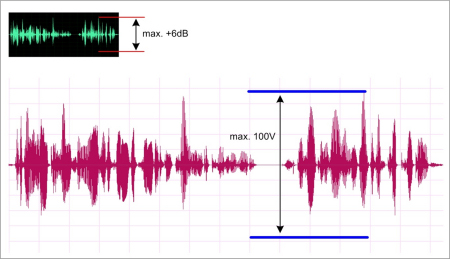
The voltage of "70V" or "100V" is NOT a real constant voltage, it is the maximum voltage defined by the system and it corresponds to the maximum input level of the amplifier. The regular voltage signal during the program transmission of music or speech is mostly far less than the maximum 70V/100V. The name 'constant voltage' corresponds to the characteristic that the voltage is not changing then the connected impedance changes (more or less connected loudspeakers). The voltage in the speaker line changes proportionally in the same way as the voltage at the audio input of the amplifier changes. The output voltage of an amplifier is determined by the input signal only. The term '70V' or '100V' defines the maximum voltage in the system in the same way as the term '+6 dB' defines the maximum level for a line signal, even if the actual level is much smaller.
Typical power rates and matching impedances (70 V system):
| 1 W | 5 W | 10 W | 30 W | 60 W | 100 W |
| 5000 Ohm | 1000 Ohm | 500 Ohm | 167 Ohm | 83 Ohm | 50 Ohm |
Also a much smaller wire diameter (AWG) can be used as in a low-impedance system (Increasing voltage and decreasing current minimizes the amount of current flowing in the wire.).
A distribution transformer is required to step up the output voltage of the amplifier so that the current flow is kept as low as possible. 25V, 70V, 100V and sometimes even more than 200V are used.
Many loudspeakers can be placed across the output by using distribution transformers. These second transformers are required at the loudspeakers to bring the voltage down to the low-voltage/high current signal needed to drive the loudspeakers. The distribution transformer usually has several taps to choose the proper power that will be drawn from the distribution line by the transformer (and finally by the loudspeaker).
The input taps of the distribution transformer let one choose the power drawn from the line and the output taps let choose the connected loudspeaker (4 Ohms, 8 Ohms, 16 Ohms).
| 35V | 50V | 70V | 100V | Ohm, primary side | |
| TAP 1 | 0.18 W | 0.37 W | 0.75 W | 1.5 W | 6400 Ohm |
| TAP 2 | 0.37 W | 0.75 W | 1.5 W | 3 W | 3200 Ohm |
| TAP 3 | 0.75 W | 1.5 W | 3 W | 6 W | 1600 Ohm |
The downside of the use of transformers is, that they always degrade the sound quality in a certain way (especially the low end).
The simplest way to wire a constant-voltage system is to parallel all the speakers on only one long run of wire. But the amount of power lost in the wire may not allow the required amount of power to get to the farthest loudspeaker. And if there should be a short on the wire run, it would take down the entire system.
The better approach is to wire seperate rows of loudspeakers. These separate wire runs can be disconnected for troubleshooting and could be powered by different power amplifiers. They also can be switched differently (see paging switch).
It must be calculated with a certain power loss in the transformers (step-up and step-down transformer). Usually it will be 10 to 15 % for both transformers together.
The load impedance of any loudspeaker transformer determines how much power is drawn from the constant voltage line. The transformer usually has several taps to choose the proper power that will be drawn from the distribution line by loudspeaker through the transformer.
Typical power rates and matching load impedances (70V system):| 1 W | 5 W | 10 W | 30 W | 60 W | 100 W |
| 5000 Ohm | 1000 Ohm | 500 Ohm | 167 Ohm | 83 Ohm | 50 Ohm |
Wires have a certain resistance that is in series with the speaker. Because of the resistance in the wire between the power amplifier and the speaker the speaker will 'lose' power to the wire. With larger (thicker) wire the loss is less because a thicker wire has less resistance.
The wire acts like a voltage divider and cuts the amount of voltage from the amplifier available to the speaker.
For instance: A 200 feet cable AWG 20 has a resistance of about 4 Ohms, a 25 feet cable AWG 12 has a resistance of about 0.08 Ohms !
Zt = E˛ / P = 70,7 * 70.7 / 100 = 4998.5 / 100 = 49.98 the total load impedance is 50 Ohms!
From example 1: The cable run is 300m and the wire is 1 qmm with a resistance of about 18.5 Ohms/km.
The cable resistance is = 300m * 18 Ohms/km * 2 * 1/1000 = 10.8 Ohms
( Factor 2 for two wires in a cable, factor 1/1000 for the km in the wire resistance )
The cable adds a resistance of 10.8 Ohms to the speaker impedance of 100 Ohms (the above 100V system in the Example 1). The amp would 'see' about 111 Ohms. With the available 100V this will produce a power of about 90 Watts, reaching the speaker. This is 100% less that the full 100W that would be produced by connecting the speaker directly with a very short cable. 10% less is 1 dB less. 1 dB less is the maximum line loss acceptable !
Insertion loss is the loss of power through the transformer. If the loss is 3 dB, half of the amplifier's power is lost. You should not have more than 1 dB loss in any audio transformer. The insertion loss of the transformers is measured at 1000 Hz. One problem is here that most of the power in the sound spectrum is below 400 Hz and the insertion loss at 1000 Hz could give a false information. All transformers should be tested at 60 Hz too.
| Insertion Loss | Power Consumption |
| 1.0 dB | 1.259x |
| 1.5 dB | 1.413x |
| 2.0 dB | 1.580x |
| 2.5 dB | 1.770x |